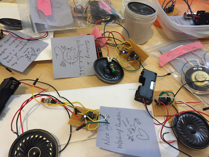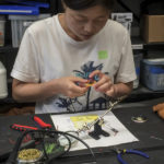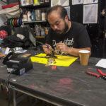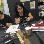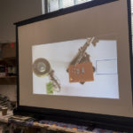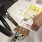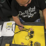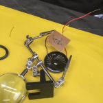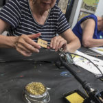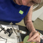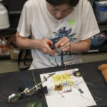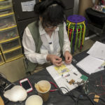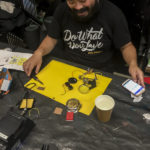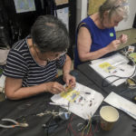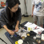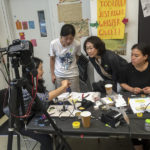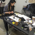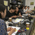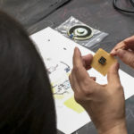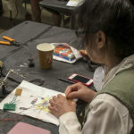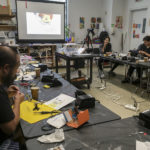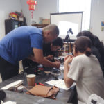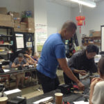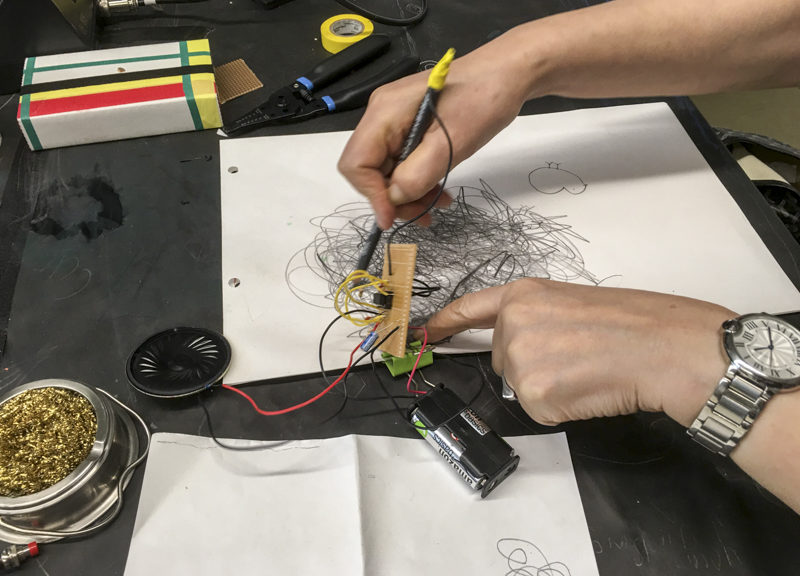
Transferring the tested circuit from a mini breadboard to a circuit board can be challenging. We assembled the sound machine together through a live camera projection. Participants soldered a piece by a piece checking the quality of their soldering together. As the first step of circuitry, the timer NE555 centered on the schematics. We positioned and soldered all eight pins guiding a next step. The timer’s orientation is indicated by a circle mark as a top. The pins are in an order of from top bottom left to bottom top right (see the below image). We soldered up each part, 10K resistor, 0.01uF capacitor, 300K resistor, 680pF capacitor, 10uF 25V 105C Radial Electrolytic Capacitor. That was the easy task. Participants stumbled on connecting the pins to the wire that we went on a tutorial bridging two pins once more. The week five went by quickly as we expected, though they saw their first sound machine realized by their own hands.
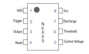
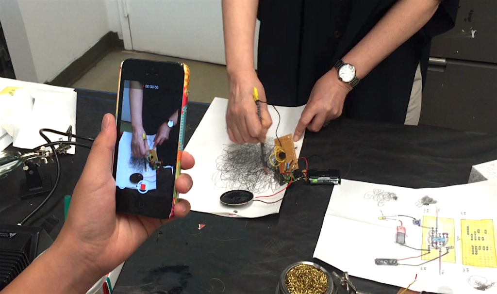
미니브레드 보드에 실험한 회로를 회로 기판에 이동하는 것이 힘들 수 있습니다. 우리는 라이브 카메라 프로젝션으로 함께 사운드 기계를 만들어 보았다. 참가자들은 한 단계 마다 서로의 납 땜의 질을 확인했다. 회로의 첫 단계로서, 타이머 NE555은 설계도의 가장 중요한 가운데에 있다. 타이머의 위쪽은 원모양이 왼쪽위에 표시하고 있다. 핀의 순서는 위 왼쪽에서 아래로, 오른쪽 아래에서 위로 읽는다. 우리는 NE555 모든 8개 핀 납 땜을 시작으로 각 부품, 10킬로미터 저항기, 0.01uF 콘덴서,300K 저항기, 680pF 콘덴서, 10uF 25V 105C 요골 전해 콘덴서를에 납 땜을 했다. 제일 쉬운 부분이 끝났다. 납떔한 두부분을 연결하는 것은 아마도 납떕질의 가장 중요하면서도 힘든 과정이다. 참가자들은 전선을 핀에 연결하는 부분을 다시한번 지도받았다. 자신들이 첫번째 소리 기계 그들 자신의 손에 의해서 실현되는 것을 보고 기대했던 주 5는 여나없이 빨리 지나갔다.